


Water and temperature monitoring methods are essential throughout varied industries, together with the chemical, pharmaceutical, and textile sectors. They assist preserve exact liquid ranges and secure temperatures—components important to making sure product high quality. In chemical processing, as an example, each parameters should stay inside outlined limits all through the operation.
This method makes use of contact or non-contact water stage sensors together with a probe-type temperature sensor. A digital show supplies steady, real-time monitoring of liquid stage and temperature.
Conventional methods usually depend on primary LED indicators or 7-segment shows, which don’t present precise water quantity (in litres) or exact temperature (in levels Celsius). Some fashionable methods do function LCDs that show each parameters with numerical accuracy.

This method demonstrates water stage and temperature monitoring on a ten.92cm (4.3-inch) TFT LCD utilizing graphics and colour-changing animation of water filling a tank, together with a rising temperature bar graph. Fig. 1 exhibits the prototype on the left and a snapshot of the TFT show on the precise. The parts required to construct the system are listed in Desk 1.
| Desk 1 Invoice Of Supplies | |
| Parts | Amount |
| Arduino Nano (MOD1) | 1 |
| Temperature sensor DS18B20 (S1) | 1 |
| HC-SR04 ultrasonic sensor (S2) | 1 |
| 10.92cm (4.3-inch) SPI TFT show (MOD2) | 1 |
| Resistors 1kΩ (R1-R6) | 6 |
| Resistors 2.2kΩ (R7-R12) | 6 |
| Resistor 4.7kΩ (R13) | 1 |
| USB connector | 1 |

Circuit and dealing
Fig. 2 exhibits the {hardware} connections, and Fig. 3 exhibits the circuit diagram. The system is constructed across the HC-SR04 ultrasonic sensor (S2), DS18B20 waterproof temperature sensor (S1), Arduino Nano (MOD1), a ten.92cm (4.3-inch) SPI TFT show (MOD2), and some different parts. The TFT show (480×320 decision) exhibits the precise water stage (in litres) and temperature. Resistors are used for sign conditioning, pull-up, and voltage-level shifting.
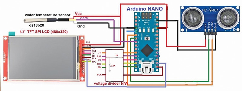
The TRIG and ECHO pins of the ultrasonic sensor hook up with D4 and D3, respectively, to measure distance by calculating the time between pulse transmission and echo reception. The TFT show connects via SPI traces: SCK to D13, SDI to D12, SDO to D11, DC to D10, RST to D9, and CS to D8. Resistors R1 via R12 make sure the secure operation of the TFT module.

The Arduino is powered through the 5V rail, with a standard floor throughout all modules. The HC-SR04 measures the space to the water floor to compute the extent, whereas the DS18B20 supplies temperature knowledge. The Arduino processes each and shows them graphically, utilizing tank animations and bar graphs. The resistors defend parts throughout operation.

Sorry! You can’t learn this publish additional, as that is for EFY PRIME subscribers solely.
