
Researchers on the College of California, Berkeley, have developed a novel 3D printing approach able to fabricating ultra-light, structurally complicated antennas utilizing a charge-guided multi-material deposition course of. The tactic, referred to as Cost Programmed Deposition (CPD), permits the direct 3D printing of electromagnetic gadgets with intricate metal-dielectric architectures, eliminating the necessity for conventional lithographic or subtractive manufacturing steps.
Revealed in Nature Communications, the examine presents CPD as a flexible platform for producing a variety of antenna sorts, together with transmitarrays, Vivaldi antennas, and horn antennas, utilizing commercially obtainable desktop SLA printers. The approach permits for the mixing of high-conductivity metals and varied dielectrics inside a single construct, decreasing half depend, weight, and manufacturing complexity.
3D printing guided by floor polarity
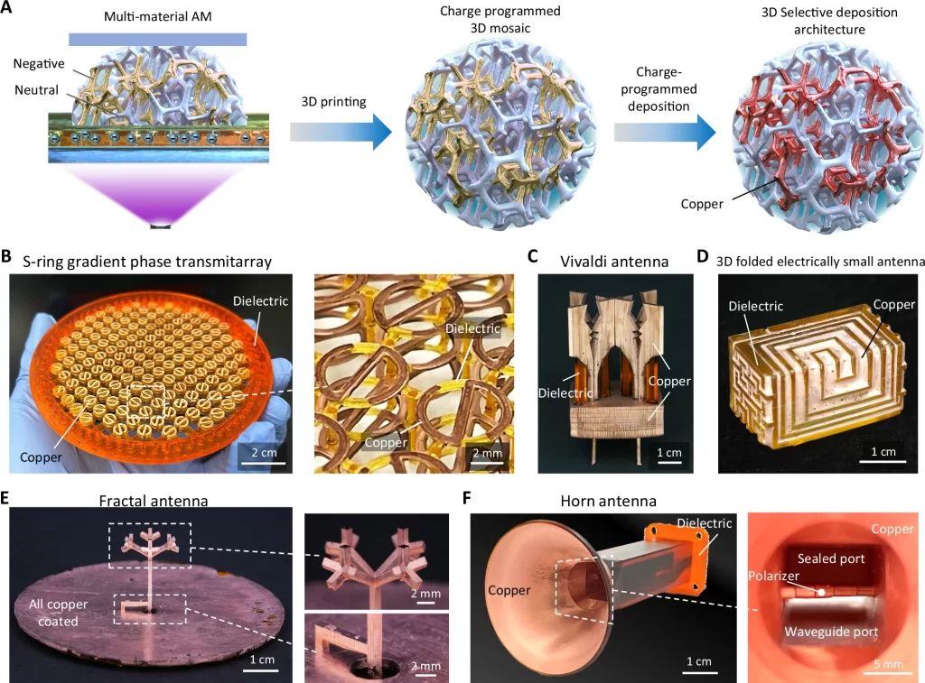
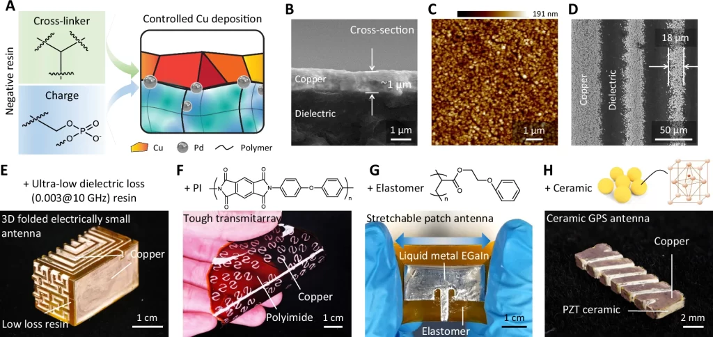
On the core of the CPD course of is a charge-based materials programming methodology. Throughout stereolithographic printing, the researchers assign completely different cost polarities, optimistic, detrimental, or impartial, to varied areas of a printed patterned dielectric substrate. This “cost mosaic” determines the place metals adhere throughout selective electroless plating. Solely oppositely charged areas appeal to the metallic ions, enabling exact, toolpath-free patterning of conductive traces in three dimensions.
Following printing, the half undergoes a chemical remedy sequence; palladium ions are deposited as a catalyst, then copper is plated onto the charged areas. The method yields easy, crack-free copper paths with a conductivity of 4.9 × 10⁷ S/m, corresponding to annealed copper and nicely suited to high-frequency purposes.
Structural and practical complexity
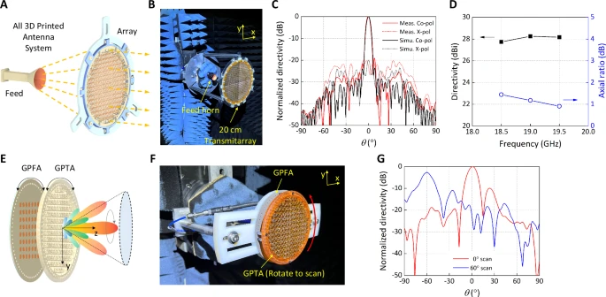
The researchers demonstrated the strategy’s flexibility by fabricating a circularly polarized 19 GHz transmitarray antenna that includes three layers of interpenetrating S-ring unit cells. Weighing simply 5 grams, the transmitarray achieved a 94% weight discount in comparison with an equal PCB-based design, whereas sustaining excessive directivity and acquire.
A horn antenna, additionally fabricated utilizing CPD, includes a septum polarizer and meandered waveguide transition, demonstrating the strategy’s functionality to create complicated inner channels. Extra examples included folded miniaturized antennas, fractal geometries, and stretchable designs utilizing elastomers and liquid metallic alloys.
To beat construct quantity limitations, the workforce designed a modular tiling technique for antenna arrays, enabling the meeting of bigger aperture methods with out efficiency loss.
Towards scalable, low-cost antenna manufacturing
Not like different multi-material additive strategies, CPD doesn’t require a number of printheads, substrate alignment, or high-temperature sintering. As a substitute, it leverages customary SLA printers with handbook resin swapping, making the method each cost-effective and accessible. Supplies explored embody polymers, polyimide, ceramics, and elastomers, with tailor-made resin formulations to help cost modulation and copper deposition.
This analysis considerably lowers the barrier to fabricating customized, high-performance antennas for space-limited or weight-sensitive platforms. CPD permits speedy prototyping, design iteration, and on-demand manufacturing with out the fabric waste and complexity of subtractive strategies or multi-step meeting.
Future developments will give attention to automating resin dealing with, increasing materials palettes, and integrating different practical coatings, comparable to magnetic or piezoelectric movies, for next-generation digital methods.
The authors see fast purposes in CubeSats, 6G base stations, and transportable or wearable gadgets, particularly the place weight, geometry, and efficiency have to be tightly managed.

Developments in 3D printed antenna analysis
As antenna calls for evolve, 3D printing continues to emerge as a key enabler of design flexibility and efficiency enhancements. As an illustration, researchers on the College of Sheffield have developed 3D printed 5G and 6G antennas that may be manufactured quicker and extra cheaply than present aerials, demonstrating radio frequency efficiency akin to that of conventionally produced antennas.
Equally, the US Navy Analysis Laboratory has utilized 3D printing to manufacture optimized cylindrical antenna arrays, attaining extra compact and light-weight designs in comparison with conventional strategies.
These developments underscore the rising position of 3D printing in producing environment friendly, cost-effective, and customizable antenna options for varied purposes.
What 3D printing traits do you have to be careful for in 2025?
How is the way forward for 3D printing shaping up?
Subscribe to the 3D Printing Business e-newsletter to maintain up with the newest 3D printing information.
You may also observe us on LinkedIn and subscribe to the 3D Printing Business Youtube channel to entry extra unique content material.
Featured picture reveals CPD-printed horn antenna with built-in polarizer. Picture through Nature Communications / UC Berkeley.
