

In trendy houses, residences, and places of work, a number of entrance doorways are frequent. Historically, every door requires a separate doorbell, which will increase price and might confuse residents. Listening to a bell with out understanding whether or not it’s the essential entrance or the again door is a frequent inconvenience. To handle this, a single bell system has been designed for 2 doorways, utilizing a standard bell that produces two distinct sound patterns relying on which door’s change is pressed. Fig. 1 reveals the system prototype with out its transformer.

| Elements Record |
| Semiconductors: IC1 – LM7805, 5V regulator IC2 – LM556 timer BR1 – 1A bridge rectifier Resistors (all 1/4-watt, ±5% carbon): R1, R2, R4, R5 – 1kΩ R3 – 68kΩ R6 – 22kΩ Capacitors: C1 – 1000µF, 35V electrolytic C2, C4 – 100nF ceramic disc C3, C5, C6 – 10nF ceramic disc C7 – 220µF, 35V electrolytic Miscellaneous: CON1 – 2-pin connector LS1 – 8Ω, 0.5-watt speaker S1, S2 – Bell change X1 – 230V AC main to 15V AC, 500mA secondary transformer |
Circuit and Working
Fig. 2 reveals the circuit diagram of the dual-tone single bell system for 2 doorways. It makes use of a well-liked LM556 dual-timer IC, which has two 555 timers constructed into one package deal. The whole circuit is split into three sections: the ability provide part, the tone technology part, and the output part.
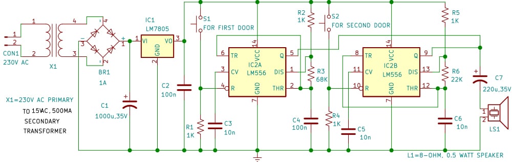
The facility provide part is constructed round transformer X1 and LM7805 (IC1) and gives a regulated 5V DC provide. A step-down transformer (X1) reduces the mains 230V AC voltage to 15V AC, which is then rectified by a bridge rectifier (BR1). An electrolytic capacitor (C1) smooths the DC output, whereas one other capacitor (C2) removes high-frequency noise. Lastly, the LM7805 voltage regulator ensures a gentle and ripple-free 5V DC, which powers the LM556 timer IC and related elements.

The tone technology part, constructed round LM556 (IC2), produces two tones. This IC has two inbuilt timers in a single package deal. Each are configured in astable mode to generate oscillating indicators. The primary timer (IC2A) is activated when change S1 is pressed at door 1. Its frequency is decided by resistors R2 and R3 and capacitor C4, producing a selected tone. Equally, the second timer (IC2B) is triggered by change S2 at door 2, and its frequency is ready by resistors R5 and R6 and capacitor C6. Because of the distinction in tones, one can simply distinguish which doorbell has been activated.
Tone 1 is ready by resistors R2 and R3 and capacitor C4 round IC2A. Rising C4 decreases the frequency to supply a lower-pitched tone, whereas lowering it will increase the frequency for a higher-pitched tone. Adjusting R2 additionally adjustments the tone inversely with frequency.
Tone 2 is ready by resistors R4 and R5 and capacitor C6 round IC2B. Rising C6 lowers the frequency for a deeper tone, whereas lowering it raises the frequency for a sharper tone.
The output part, constructed round a standard speaker (LS1) and capacitor C7, produces two distinct tones. The speaker converts the oscillating square-wave indicators into audible sounds. As a result of the timers generate totally different frequencies, the speaker emits two clearly distinguishable sound patterns. This ensures that, with a single speaker, residents can simply establish which doorbell change has been pressed, based mostly on whether or not the sound is higher-pitched or lower-pitched.
Total, the ability provide gives a secure 5V DC to the circuit. Urgent change S1 triggers IC2A, producing Tone 1, whereas urgent change S2 triggers IC2B, producing Tone 2. The speaker then rings on the corresponding frequency. Since each tones are distinct, the listener can shortly recognise whether or not the decision is from door 1 or door 2. This makes the system easy, sensible, and extremely environment friendly for houses, residences, or places of work with a couple of entrance.
Building and Testing
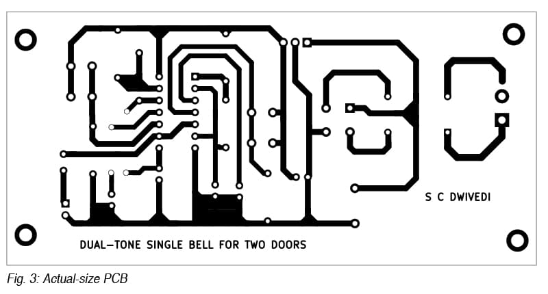
An actual-size, single-sided PCB format for the dual-tone single bell system for 2 doorways is proven in Fig. 3, with its part format in Fig. 4. After assembling the circuit on the PCB, enclose it in an appropriate field.
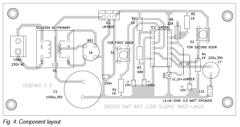
For PCB meeting, begin with small components, akin to resistors, ceramic capacitors, and jumpers, adopted by the rectifier, regulator IC, timer IC, and electrolytic capacitors. Mount connectors for AC enter, speaker, and switches, and solder them. Home the assembled PCB in a plastic enclosure with exterior connections for the transformer, switches, and speaker.
For testing, first test the regulated 5V output with the LM556 eliminated. As soon as verified, insert the LM556 and join the speaker. Urgent change S1 ought to give Tone 1, whereas S2 produces a definite Tone 2. If each sound related, test the resistor and capacitor values. If silent, test the provision and IC connections. After confirming operation, set up the switches on the doorways and place the speaker centrally.
Set up steps
- Set up the door push switches S1 and S2 on the entrances
- Mount the speaker (LS1) at a central location inside the home the place it’s clearly audible, making certain it’s securely mounted and guarded
- Join the 230V AC enter to connector CON1 and maintain the cupboard in an appropriate place
- Join the speaker to the output connector LS1
- Insulate all AC components and take a look at the system.
Bonus: You’ll be able to watch the full video tutorial of this mission.
