

As we develop by means of our lives, we realise that we should deal with our earlier and subsequent technology members and it’s a problem to keep up their treatment schedules in the course of as we speak’s fast-paced world, particularly for aged members, sufferers who’re home-bound and youngsters who’re but to develop their understanding. Including extra complexity to that is the very fact, that some medicines needn’t be taken each day, however at an interval of 2-3-4 days. The Senior Pillbox goals to offer a low-cost, absolutely digital circuit-based resolution with minimal human intervention. We simply want to make sure that we’ve refilled their each day dosage for all the week and naturally, an uninterrupted energy provide!
The system is supposed to automate each day treatment reminders with the assistance of each visible and audio alerts. It’s famous that sufferers typically get irritated by noise intervention. To make sure that the Audio part (BT66/UM66 half, right here) isn’t activated by inaccurate alerts, we’ve supplied optical isolation utilizing an opto-coupler IC. Every single day, the reminder circuit lights up an LED (for 10 seconds within the current case) comparable to the particular day of the week, and moreover, an audio indication is activated for a pre-decided length (10 seconds, within the current case) for each hole of 24 hours. As soon as the alert is activated, the system goes again to calculate the subsequent hole interval of the 24-hour cycle. For demonstration functions, we’ve chosen 10 10-second (as an alternative of 24-hour) interval and an alert length of 1 sec (as an alternative of 10 seconds) for ease of video recording.
The proposed setup is used as a mixed LED and buzzer alert meeting. Determine 1 reveals the creator’s prototype of all the setup. Determine 2 represents the block diagram of the Undertaking.


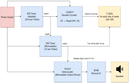
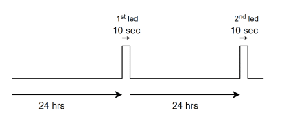
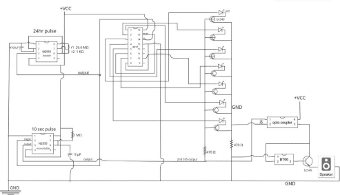
The Circuit is kind of easy to function. The primary 555 timer (24 hr Astable mode) is linked to the clock pin of the CD4017 and likewise to the set off pin of the second 555 timer. The second 555 timer (10s Monostable mode) has its output linked to the enter of the optocoupler (PC817) and to the frequent cathode of the day LEDs. Every Q0 to Q6 output of the CD4017 is linked to a separate LED to symbolize the corresponding days of the week. The output of the optocoupler is linked to the set off pin of the BT66 audio module. The BT66 output is fed to the bottom of a BC549 transistor, which drives the speaker linked between its emitter and floor provide. You may confer with determine 3 for an understanding of the timing diagram and determine 4 for the connections of the proposed circuit diagram. Desk 1 is the invoice of supplies.
Invoice of Supplies
| Parts | Rely | Description |
| 555 Timer IC | 2 | For setting a 24-hour time in 555 IC |
| CD4017 Decade Counter | 1 | For 7-day LED sequencing |
| BT66 Audio Module | 1 | Performs an alert sound by means of the speaker |
| BC549 Transistor | 8 | 7 To modify LEDs ON/OFF & 1 for the speaker |
| Optocoupler (PC817) | 1 | To isolate BT66 from 555 IC |
| LEDs | 7 | One per day (Mon–Solar) |
| Resistor1 (26.6 MΩ) (AMV) | 1 | For setting a 24-hour time in 555 IC |
| Resistor2 (1 KΩ) (AMV) | 1 | For setting 24hr time in 555 IC |
| Resistor (1 MΩ) (MMV) | 1 | For setting 10sec time in 2nd 555 IC |
| Capacitor (4700 µf) (AMV) | 1 | For 555 timing (24 hr) |
| Capacitor (9/10 µf) (MMV) | 1 | For 555 timing (10s) |
| Speaker (8Ω) | 1 | For taking part in the sound |
| Breadboard | 2 | For prototyping all the circuit |
| Jumper Wires | – | For all connections |
| Energy Provide (5V) | 1 | Battery or DC Adapter |
| Diode | 1 | To stop the other move between the optocoupler pins |
Working
The principle elements of the gadget are two IC 555 timer ICs, a CD4017 decade counter coupled through an optocoupler IC to the BT66 audio module. The IC 555 timers type the system’s core, every configured for a definite timing perform. The primary IC 555 timer operates in Astable mode and serves because the system’s primary clock, producing a pulse as soon as each 24 hours. This pulse advances the CD4017 counter to point the present day and triggers the second IC 555 timer. The second IC 555 timer is configured in Monostable mode and is accountable for producing a 10-second pulse. This pulse prompts each the LED comparable to the present day and the speaker, guaranteeing a mixed visible and auditory reminder.
The values of the elements are:
For (Astable 24 hr)
R1: 26.6 MΩ
R2: 1 KΩ
Capacitor:4700 µf
For (Monostable 10 sec)
Resistor: 1 MΩ
Capacitor: 9/10 µf
The CD4017 decade counter performs a vital position in monitoring the times of the week. It advances one output pin every time it receives a pulse from the astable timer, lighting up one of many seven LEDs labelled from Sunday to Saturday. As soon as it reaches the seventh output, the counter resets to the primary output, thus making a steady weekly cycle.
The optocoupler acts as a security and isolation part within the circuit. It permits the monostable timer to set off the BT66 audio module with none direct electrical connection, enhancing reliability and stopping interference between the logic and audio sections. The BT66 audio module, when triggered, performs a preloaded sound for 10 seconds by means of a speaker, managed through a BC549 transistor that acts as an digital swap. Collectively, these elements create a dependable and user-friendly system that ensures well timed reminders for treatment consumption every day.
Connection among the many primary elements:
| IC555A (24 hr) | IC555B (10 sec) | IC 4017 | BT66 | Speaker | PC817 | BC549 Speaker | |
| GND | Pin 1 Pin 5 through 0.01 µF Pin 2 & 6 through 4700µF |
Pin 1 Pin 5 through 0.01 µF Pin 6 & 7 through 9µF |
Pin 13 Pin 8 |
Pin 1 | -(ive) finish | Pin 2 through 470 Ω | – |
| +5V | Pin 4 Pin 8 Pin 7 through 26.6 MΩ 1 KΩ between Pin 6 & 7 |
Pin 4 Pin 8 Pin 6 & 7 through 1MΩ |
Pin 16 | – | – | Pin 4 | – |
| IC 555A o/p (Pin 3) |
Pin 3 | Pin 2 | Pin 14 | – | – | – | – |
| IC 555 B o/p (Pin 3) |
– | Pin 3 | – | – | – | Pin 1 | – |
| Not linked | – | – | Pin 9 Pin 11 Pin 12 |
– | – | – | – |
| – | – | – | – | – | +(ive) finish | – | Emitter |
| – | – | – | – | Pin 2 | – | Pin 3 | Collector |
| – | – | – | – | Pin 3 | – | – | Base |
IC 555A is for a 24-hour hour duration-Astable Mode of operation
IC 555B is for 10 10-second duration-Monostable Mode of operation
For Pins 1-7, 10 and 15 of IC CD4017, please examine the desk CD4017 mapping to weekday LEDs.
