
Half certainly one of an in-depth take a look at how you can use assist materials. First up: single extrusion. Study profitable design issues and how you can use assist materials to create advanced prints.
Posted on December 21, 2016
by
Scott Cahoon
When designing fashions for 3D printing, the prudent designer will be sure that unfavourable house is minimized and that the positioning of the mannequin on the printer assists in navigating or mitigating that house. Nonetheless, any designer who has been across the block a couple of times is aware of that there’ll come a time when using helps can’t be prevented. With that in thoughts, this text will discover some issues throughout design to mitigate printing over unfavourable house and to enterprise extra in-depth on using helps whereas printing.
Beginning Out
An skilled designer is aware of that simply because an concept or product could be designed doesn’t essentially imply that it may be made. There are limits in fabrication processes that may dictate what kind of designs are attainable. For instance, machining works effectively for components with exterior surfaces, however surfaces on the inside may pose an issue because the software wanted to make the floor might not be capable of entry that specific geometry. The identical is true through the injection molding course of. Sharp angles and “hidden” surfaces are difficult to create.
These points are the rationale why 3D printing is such a robust software. For the reason that half is constructed utilizing an additive course of, many beforehand laborious to succeed in geometries could also be accessed with little effort. Nonetheless, there are limitations to 3D printing that the designer wants to remember. These limitations are sometimes printer particular, so information of your printer’s capabilities are of paramount significance.
Printer Limitations
The primary consideration is how effectively your printer offers with overhangs. The rule of thumb is to keep away from designing overhangs the place the vertical floor angle between the vertical fringe of the decrease layers and the sting of the overhang is lower than 45 levels. Many printers might be able to navigate angles better than 45 levels, however not all printers might be profitable. To know the overhang capabilities of your printer, please check with the Overhangs part of A Information to Understanding the Tolerances of Your 3D Printer.
One other consideration is how effectively your printer is ready to bridge. Bridging is outlined because the printer’s capacity to print a stable layer between gaps or unfavourable house in decrease layers with out using helps. Once more, bridging is printer dependent, however an excellent rule of thumb is to maintain the bridging distance lower than 50mm. Additionally, for a bridge to be efficiently printed, there must be a decrease contiguous wall or column edge (see Determine 2) between each ends of the bottom of the bridge. Please check with the Bridging part of A Information to Understanding the Tolerances of Your 3D Printer for added data and to find out your printer’s limitations.
Design Concerns
Now allow us to take a look at mannequin design. When coping with overhangs, it could be attainable to realize the specified kind and performance by designing the half in order that the overhang is lower than a forty five diploma angle from vertical. If the designed half requires an overhang angle better than 45 levels, then an arc or chamfer (see Determine 1) could also be utilized on the floor subsequent to the unfavourable house to help within the half’s printability.

Determine 1: 70 Diploma (Vertical) Angle With Radius and Chamfer
When bridging, make it possible for the mannequin has an excellent base wall or column on every finish of the bridge. Additionally, bridges are direct, straight line photographs. When navigating unfavourable house, don’t design options or bridges with curves or angles until you will use helps. A printer doesn’t do effectively when transitioning from straight traces and can go away filament residue alongside the print path of the characteristic (see Determine 2).
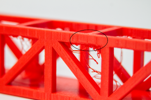
Determine 2: Bridge With No Finish Column
Lastly, a designer might want to divide or phase the mannequin into particular person printed components to be assembled upon completion. This can be extra fascinating than utilizing helps, particularly if the mannequin is multifaceted with many floor angles. A superb overview of segmented designs and printed assemblies could also be discovered at Printing Exterior the Field: Exceeding the Construct Quantity of Your Printer and MatterHackers Lab: Design 3D Printed Assemblies.
Helps
Within the prehistoric instances of desktop 3D printing (about 4 years in the past), helps had been a uncared for and neglected characteristic of 3D printing practitioners. Helps had been usually tough to generate and much more tough to take away. Now, it’s a lot simpler to print with helps and elimination isn’t any extra sophisticated than some other normal ending course of. The secret is realizing when to make use of them and how you can set them up for printing.
Helps are used when all different strategies of mitigating unfavourable house have been exhausted. Creating helps is pretty straight ahead when utilizing MatterControl. When adjusting the settings in MatterControl, the “Assist Materials” part could also be positioned underneath the “Basic” tab underneath “Settings” (see Determine 3). The “Assist Materials” part reveals a listing of choices which may be set relying on the kind of unfavourable house to be mitigated.
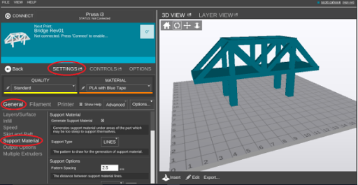
Determine 3: Creating helps in MatterControl
For instance, if the mannequin incorporates many surfaces that fluctuate over a brief distance, then lowering the “Sample Spacing” will be sure that all surfaces subsequent to unfavourable house might be supported. One other instance can be the adjustment of the “Assist %” relying on the kind of characteristic to be supported. If the mannequin floor space subsequent to the unfavourable house is giant, then a better “Assist %” could also be required to offer a extra stable assist basis.
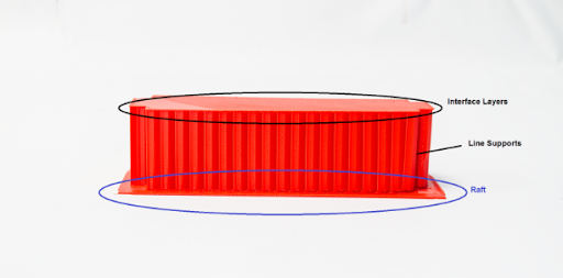
Earlier than delving into specifics, allow us to take a look at the essential anatomy of a assist configuration. The essential anatomy contains the kind of assist (“Assist Kind”), the interface layer (“Interface Layers”), the perimeter (“Create Perimeter”) and an optionally available raft (“Skirt and Raft”) (see Determine 4). A raft might help in mattress adhesion for the primary assist layer, however shouldn’t be important.
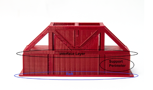
Determine 4: Interface Layer, Assist Perimeter, and Raft
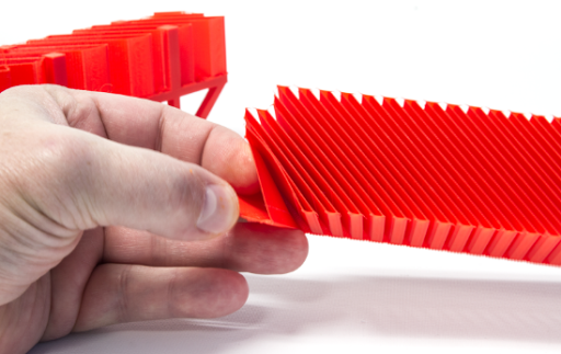
The kind of assist is nothing greater than the geometric sample of the bottom assist, e.g. traces, grid, and so forth. The interface layer is the stable layer between the highest of the helps and the underside of the half. This layer is extraordinarily useful when eradicating helps from the floor of the mannequin since all of the assist construction is linked to the interface layer and can normally separate from the mannequin in a single pull (see Determine 5). The perimeter encompasses the outside of the assist footprint and gives improve stability for the assist construction. Lastly, a raft could also be included for assist mattress adhesion.
Determine 5: Discover the Easy Floor of the Interface Layers Upon Elimination
Assist Specifics
Desk 1 lists all of the settings that the designer and 3D printing practitioner might modify to assemble the specified helps. For this text seven bridges had been printed to spotlight the completely different settings. Use these fashions as a information and be at liberty to experiment with completely different configurations to acquire the very best outcomes.

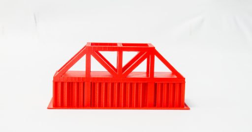
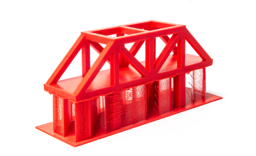
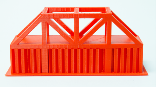
Determine 6: Bridge 1 Entrance View With 2.5mm Sample Spacing Line Helps
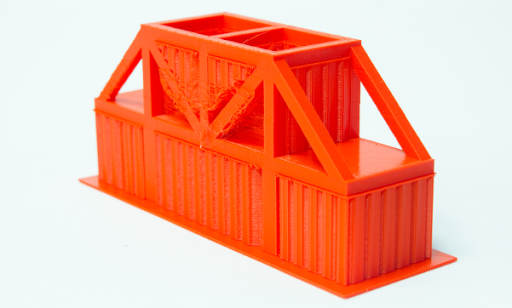
Determine 7: Bridge 1 Angled View
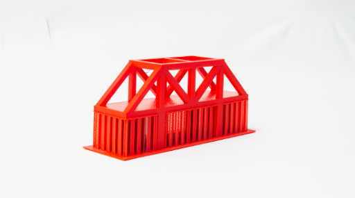
Determine 8: Bridge 2 Angled View With 5mm Sample Spacing Line Helps
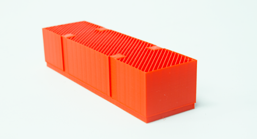
Determine 9: Bridge 2 Backside View With out Raft
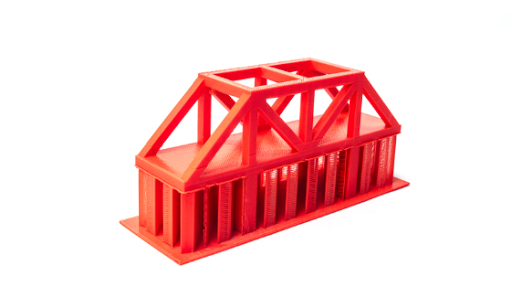
Determine 10: Bridge 3 Angled View With 10mm Sample Spacing Line Helps
Determine 11: Bridge 3 Backside View

Determine 12: Bridge 4 Backside View With 10% Assist Proportion and 10mm Sample Spacing
Determine 13: Bridge Backside View With 50% Assist Proportion and a couple of.5mm Sample Spacing
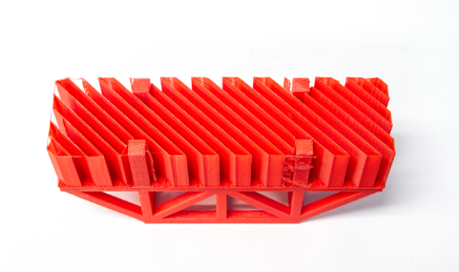
Determine 14: Bridge 5 With No Interface Layers
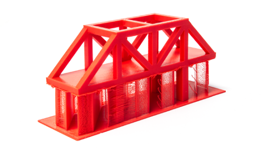
Determine 15: Bridge 6 With Helps All over the place

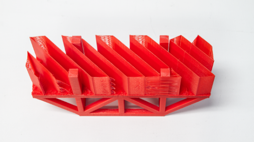
Determine 16: Bridge 7 With Helps All over the place and Assist Perimeter
Determine 17: Backside View of two.5mm Sample Spacing of Line Helps With Assist Perimeter
From expertise, the settings which are incessantly adjusted when configuring helps are “Sample Spacing”, Assist %”, “X and Y Distance”, “Air Hole” and “Assist All over the place”.
Modifications in sample spacing determines the quantity of helps which are used. Often, the spacing is much less if there are quite a few surfaces spanning a small distance within the X and Y instructions. For flatter mannequin surfaces over unfavourable house, the practitioner might find a way use better sample spacing distances and obtain the identical desired assist impacts. Simply bear in mind that spacing lower than 10mm permits for a good to good interface layer with a corresponding good half floor end whereas spacing better than 10mm is usually problematic.
Adjusting the assist share determines the density of the assist. For big overhangs or surfaces over giant unfavourable areas, a better assist share could also be advisable. For small overhangs or options, a decrease share might suffice. Figures 12 and 13 present the pliability of the helps at 10% and 50% “Assist %” respectively.
Adjusting the “X and Y Distance” comes into play when putting helps subsequent to components of a mannequin that abut unfavourable house within the X and Y instructions. The default distance is .7mm and could also be elevated if outstanding options subsequent to the unfavourable house want to permit extra room for assist elimination (see Determine 18). This can be advantageous when there are a number of floor adjustments within the X and Y instructions.
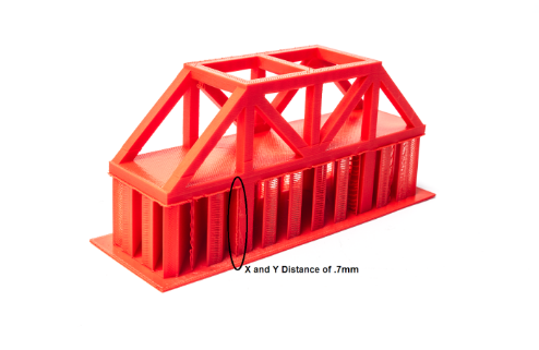
Determine 18: X and Y Distance of 0.7mm
Air gaps are the quantity of distance between the interface layer and the underside of the mannequin floor (see Determine 19). The better the air hole, the simpler it’s to take away the assist construction. Simply bear in mind that bigger air gaps might trigger stringing on the underside of the mannequin. The default air hole setting is .3mm.
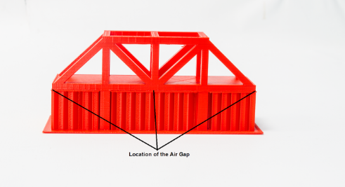
Determine 19: Location of the Air Hole
Lastly, “Assist All over the place” implies that helps are generated throughout all unfavourable areas within the mannequin, no matter location (see Determine 16). Consequently, helps are generated between the underside of the mannequin and the print mattress in addition to in areas in the course of the mannequin the place unfavourable house exists.
To Sum It All Up
One last tidbit is to acknowledge that kind and performance because it pertains to design usually decide whether or not helps are essential. Often, if a component is supposed to offer a sure operate, then usually it could be designed the place helps are usually not wanted. The designer might be able to add chamfers, radii or phase the half whereas attaining the specified performance in the long run product. Nonetheless, when kind is crucial consideration, helps usually are essential to finish a profitable print. Be happy to experiment as you go and simply notice that helps are an support to your efforts and never a detractor. Above all else, bear in mind to have enjoyable and to benefit from the 3D printing journey.
