
A frequency-dependent change designed for PSpice simulation empowers specialists to handle challenges in superior techniques, seamlessly integrating into numerous digital circuits.
Switches could also be utilized in any system/circuit in UHF or larger radio bands that have to route alerts by means of a number of paths. Switches in several configurations are utilized in ATE (automated take a look at tools) techniques. Strong state switches could be divided into two main classes: mechanical, relay-operated, PIN diode and FETs. They can be utilized,
- to modify a single sign between double outputs,
- to attach totally different a number of outputs delivering alerts to port connections in parallel,
- to route change (bypass) a voltage round moderately than by means of a circuit factor or system.
Design and modelling of a voltage/current-controlled analogue behavioural mannequin change suitable with PSpice circuit simulation software program are described with examples within the frequency area.

Simulation methodology
The PSpice methodology to acquire an equal circuit for various switches utilizing analogue behavioural modelling is described. Different works on this discipline used totally different configurations utilizing polynomial voltage/present supply fashions of the unique PSpice program.
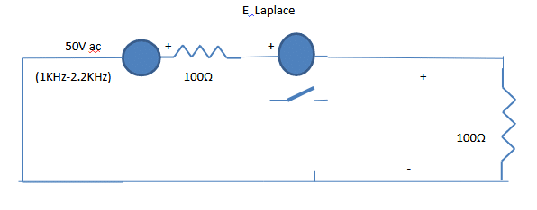
Desk I describes (Fig: 1) the PSpice process to acquire frequency-dependence, which behaves as quick at 1700Hz and turns into open circuit at different working frequencies of Fig: 1 [equivalent to performing switching (on/off) action]. The E Laplace in Fig: 1 describes an on/off resistor utilizing analogue behavioural modelling of PSpice with the Laplace possibility.

Desk I. Frequency description of change operation (Fig: 1)
| **** 10/03/23 16:43:29 ****** PSpice Lite (October 2012) ****** ID# 10813 **** |
| Frequency-dependent change simulation |
| Circuit description |
| V2 1 0 AC 1 |
| R13 1 3 100 |
| E34 3 4 LAPLACE {I(E34)} = {(ABS(S)/(2.0*3.141592653589793)-1700)*1E8} |
| R40 4 0 100 |
| .AC LIN 13 1KHz 2.2KHz |
| .PRINT AC VM(1) VM(3) VM(4) |
| .OP |
| .finish |
| **** 10/03/23 16:43:29 ****** PSpice Lite (October 2012) ****** ID# 10813 **** |
| Frequency-dependent change simulation |
| Small sign bias answer Temperature = 27.000 DEG C |
| Node voltage |
| ( 1) 0.0000 ( 3) 0.0000 ( 4) 0.0000 |
| Voltage supply currents |
| Title Present |
| V2 0.000E+00 |
| Complete energy dissipation 0.00E+00 watts |
| **** 10/03/23 16:43:29 ****** PSpice Lite (October 2012) ****** ID# 10813 **** |
| Frequency-dependent change simulation |
| Working level data Temperature = 27.000 DEG C |
| Voltage-controlled voltage sources |
| Title E34 |
| V-source 0.000E+00 |
| I-source 0.000E+00 |
| **** 10/03/23 16:43:29 ****** PSpice Lite (October 2012) ****** ID# 10813 **** |
| Frequency-dependent change simulation |
| AC evaluation Temperature = 27.000 DEG C |
| FREQ VM(1) VM(3) VM(4) |
| 1.000E+03 1.000E+00 1.000E+00 1.429E-09 |
| 1.100E+03 1.000E+00 1.000E+00 1.667E-09 |
| 1.200E+03 1.000E+00 1.000E+00 2.000E-09 |
| 1.300E+03 1.000E+00 1.000E+00 2.500E-09 |
| 1.400E+03 1.000E+00 1.000E+00 3.333E-09 |
| 1.500E+03 1.000E+00 1.000E+00 5.000E-09 |
| 1.600E+03 1.000E+00 1.000E+00 1.000E-08 |
| 1.700E+03 1.000E+00 5.007E-01 4.993E-01 |
| 1.800E+03 1.000E+00 1.000E+00 1.000E-08 |
| 1.900E+03 1.000E+00 1.000E+00 5.000E-09 |
| 2.000E+03 1.000E+00 1.000E+00 3.333E-09 |
| 2.100E+03 1.000E+00 1.000E+00 2.500E-09 |
| 2.200E+03 1.000E+00 1.000E+00 2.000E-09 |
It may be noticed (Desk I) that as a result of switching motion at 1.7KHz, all of the voltage is transferred to the output node (4) from the node (3).
Desk II. PSpice program description of switching (Fig:2)
| **** 10/03/23 16:33:07 ****** PSpice Lite (October 2012) ****** ID# 10813 **** |
| Frequency-dependent AC change simulation |
| Circuit description |
| V2 1 0 AC 100 |
| R13 1 2 400 |
| G1 2 0 4 0 2 |
| L23 2 3 0.3 |
| R30 3 0 500 |
| C34 3 4 0.1UF |
| L46 4 6 0.1 |
| C60 6 0 0.1 |
| E45 4 5 LAPLACE {I(E45)} = {(ABS(S)/(2.0*3.14159265359)-150)*1E10} |
| R40 5 0 2000 |
| .AC LIN 4 50 200 |
| .PRINT AC VM(1) VM(3) VM(4) VM(5) |
| .OP |
| .finish |
| **** 10/03/23 16:33:07 ****** PSpice Lite (October 2012) ****** ID# 10813 **** |
| Frequency-dependent AC change simulation |
| Small sign bias answer Temperature = 27.000 DEG C |
| Node voltage |
| ( 1) 0.0000 ( 2) 0.0000 ( 3) 0.0000 ( 4) 0.0000 |
| ( 5) 0.0000 ( 6) 0.0000 |
| Voltage supply currents |
| Title Present |
| V2 0.000E+00 |
| Complete energy dissipation 0.00E+00 watts |
| **** 10/03/23 16:33:07 ****** PSpice Lite (October 2012) ****** ID# 10813 **** |
| Frequency-dependent AC change simulation |
| Working level data Temperature = 27.000 DEG C |
| Voltage-controlled present sources |
| Title G1 |
| I-source 0.000E+00 |
| Voltage-controlled voltage sources |
| Title E45 |
| V-source 0.000E+00 |
| I-source 0.000E+00 |
| **** 10/03/23 16:33:07 ****** PSpice Lite (October 2012) ****** ID# 10813 **** |
| Frequency-dependent AC change simulation |
| AC evaluation Temperature = 27.000 DEG C |
| FREQ VM(1) VM(3) VM(4) VM(5) |
| 5.000E+01 1.000E+02 9.734E+01 9.607E-02 1.921E-10 |
| 1.000E+02 1.000E+02 6.948E+01 2.753E-01 1.101E-09 |
| 1.500E+02 1.000E+02 1.831E+01 1.639E-01 1.637E-01 |
| 2.000E+02 1.000E+02 8.999E+00 1.444E-01 5.775E-10 |
| Job concluded |
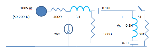
From Desk II’s description of Fig: 2, as a result of switching motion at 150Hz, the voltage at node (4) is transferred to node (5). On the remaining frequencies, as a result of open circuit nodes (5) and (4), the output voltage is zero. The E45 description in Desk II makes use of the analogue behavioural possibility of PSpice to acquire an influence change.

Desk III. Frequency description of change operation (Fig: 3)
| **** 10/14/23 16:46:40 ****** PSpice Lite (October 2012) ****** ID# 10813 **** |
| Frequency-dependent change simulation |
| Circuit description |
| Voltage AC excitation |
| I 0 3 AC 1 |
| R13 0 3 100 |
| E34 3 4 LAPLACE {I(E34)} = {(ABS(S)/(2.0*3.141592653589793)-1700)*1E8} |
| R40 4 0 100 |
| .AC LIN 13 1KHz 2.2KHz |
| .PRINT AC VM(3) VP(3) VM(4) VP(4) |
| .OP |
| .finish |
| **** 10/14/23 16:46:40 ****** PSpice Lite (October 2012) ****** ID# 10813 **** |
| Frequency-dependent change simulation |
| Small sign bias answer Temperature = 27.000 DEG C |
| Node voltage |
| ( 3) 0.0000 ( 4) 0.0000 |
| Voltage supply currents |
| Title Present |
| Complete energy dissipation 0.00E+00 watts |
| **** 10/14/23 16:46:40 ****** PSpice Lite (October 2012) ****** ID# 10813 **** |
| Frequency-dependent change simulation |
| Working level data Temperature = 27.000 DEG C |
| Voltage-controlled voltage sources |
| Title E34 |
| V-source 0.000E+00 |
| I-source 0.000E+00 |
| **** 10/14/23 16:46:40 ****** PSpice Lite (October 2012) ****** ID# 10813 **** |
| Frequency-dependent change simulation |
| AC evaluation Temperature = 27.000 DEG C |
| FREQ VM(3) VP(3) VM(4) VP(4) |
| 1.000E+03 1.000E+02 0.000E+00 1.429E-07 1.800E+02 |
| 1.100E+03 1.000E+02 0.000E+00 1.667E-07 1.800E+02 |
| 1.200E+03 1.000E+02 0.000E+00 2.000E-07 1.800E+02 |
| 1.300E+03 1.000E+02 0.000E+00 2.500E-07 1.800E+02 |
| 1.400E+03 1.000E+02 0.000E+00 3.333E-07 1.800E+02 |
| 1.500E+03 1.000E+02 0.000E+00 5.000E-07 1.800E+02 |
| 1.600E+03 1.000E+02 0.000E+00 1.000E-06 1.800E+02 |
| 1.700E+03 5.007E+01 0.000E+00 4.993E+01 0.000E+00 |
| 1.800E+03 1.000E+02 0.000E+00 1.000E-06 0.000E+00 |
| 1.900E+03 1.000E+02 0.000E+00 5.000E-07 0.000E+00 |
| 2.000E+03 1.000E+02 0.000E+00 3.333E-07 0.000E+00 |
| 2.100E+03 1.000E+02 0.000E+00 2.500E-07 0.000E+00 |
| 2.200E+03 1.000E+02 0.000E+00 2.000E-07 0.000E+00 |
| Job concluded |
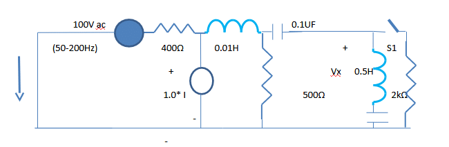
The change in Fig: 3 turns into energetic at 1700Hz as proven in Desk III, and the voltage at node (3) turns into equal to node (4).
Desk IV. Frequency description of change operation (Fig: 4)
| **** 10/15/23 12:27:19 ****** PSpice Lite (October 2012) ****** ID# 10813 **** Frequency-dependent AC change simulation |
| Circuit description |
| V2 1 0 AC 100 |
| R13 1 2 400 |
| HG1 2 0 V2 1 |
| L23 2 3 0.01 |
| R30 3 0 500 |
| C34 3 4 0.1UF |
| L46 4 6 0.5 |
| C60 6 0 0.1 |
| E45 4 5 LAPLACE {I(E45)} = {(ABS(S)/(2.0*3.14159265359)-150)*1E10} |
| R40 5 0 2000 |
| .AC LIN 4 50 200 |
| .PRINT AC VM(1) VM(3) VM(4) VM(5) |
| .OP |
| .finish |
| **** 10/15/23 12:27:19 ****** PSpice Lite (October 2012) ****** ID# 10813 **** |
| Frequency-dependent AC change simulation |
| Small sign bias answer Temperature = 27.000 DEG C |
| Node voltage |
| ( 1) 0.0000 ( 2) 0.0000 ( 3) 0.0000 ( 4) 0.0000 |
| ( 5) 0.0000 ( 6) 0.0000 |
| Voltage supply currents |
| Title Present |
| V2 0.000E+00 |
| Complete energy dissipation 0.00E+00 watts |
| **** 10/15/23 12:27:19 ****** PSpice Lite (October 2012) ****** ID# 10813 **** |
| Frequency-dependent AC change simulation |
| Working level data Temperature = 27.000 DEG C |
| Voltage-controlled voltage sources |
| Title E45 |
| V-source 0.000E+00 |
| I-source 0.000E+00 |
| Present-controlled voltage sources |
| Title HG1 |
| V-source 0.000E+00 |
| I-source 0.000E+00 |
| **** 10/15/23 12:27:19 ****** PSpice Lite (October 2012) ****** ID# 10813 **** |
| Frequency-dependent AC change simulation |
| AC evaluation Temperature =27.000 DEG C |
| FREQ VM(1) VM(3) VM(4) VM(5) |
| 5.000E+01 1.000E+02 2.506E-01 1.243E-03 2.486E-12 |
| 1.000E+02 1.000E+02 2.507E-01 5.048E-03 2.019E-11 |
| 1.500E+02 1.000E+02 2.508E-01 1.132E-02 1.131E-02 |
| 2.000E+02 1.000E+02 2.510E-01 2.151E-02 8.606E-11 |
| Job concluded |
Desk IV reveals that at 150Hz, the change is on, and the voltage at node (4) is transferred to node (5).
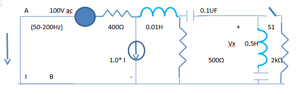
Fig: 5 reveals an AC energy circuit with a present managed present supply. Desk V reveals the netlist for the change description and operation of Fig: 5. The change is described with the image S1.
Desk V. Frequency description of change operation (Fig: 5)
| **** 10/15/23 19:35:45 ****** PSpice Lite (October 2012) ****** ID# 10813 **** |
| Frequency-dependent AC change simulation |
| Circuit description |
| V2 1 0 AC 100 |
| R13 1 2 400 |
| FG1 2 0 V2 1 |
| L23 2 3 0.01 |
| R30 3 0 500 |
| C34 3 4 0.1UF |
| L46 4 6 0.5 |
| C60 6 0 0.1 |
| E45 4 5 LAPLACE {I(E45)} = {(ABS(S)/(2.0*3.14159265359)-150)*1E10} |
| R40 5 0 2000 |
| .AC LIN 4 50 200 |
| .PRINT AC VM(1) VM(3) VM(4) VM(5) |
| .OP |
| .finish |
| **** 10/15/23 19:35:45 ****** PSpice Lite (October 2012) ****** ID# 10813 **** |
| Frequency-dependent AC change simulation |
| Small sign bias answer Temperature = 27.000 DEG C |
| Node voltage |
| ( 1) 0.0000 ( 2) 0.0000 ( 3) 0.0000 ( 4) 0.0000 |
| ( 5) 0.0000 ( 6) 0.0000 |
| Voltage supply currents |
| Title Present |
| V2 0.000E+00 |
| Complete energy dissipation 0.00E+00 watts |
| **** 10/15/23 19:35:45 ****** PSpice Lite (October 2012) ****** ID# 10813 **** |
| Frequency-dependent AC change simulation |
| Working Level Data Temperature = 27.000 DEG C |
| Voltage-controlled voltage sources |
| Title E45 |
| V-source 0.000E+00 |
| I-source 0.000E+00 |
| Present-controlled present sources |
| Title FG1 |
| I-source 0.000E+00 |
| **** 10/15/23 19:35:45 ****** PSpice Lite (October 2012) ****** ID# 10813 **** |
| Frequency-dependent AC change simulation |
| AC evaluation Temperature =27.000 DEG C |
| FREQ VM(1) VM(3) VM(4) VM(5) |
| 5.000E+01 1.000E+02 7.143E+01 3.542E-01 7.083E-10 |
| 1.000E+02 1.000E+02 7.144E+01 1.438E+00 5.754E-09 |
| 1.500E+02 1.000E+02 7.144E+01 3.224E+00 3.220E+00 |
| 2.000E+02 1.000E+02 7.147E+01 6.126E+00 2.451E-08 |
| Job concluded |
| **** 10/15/23 19:35:45 ****** PSpice Lite (October 2012) ****** ID# 10813 **** |
| Frequency-dependent AC change simulation |
| Job statistics abstract |
Switching recruitment for frequency-dependent techniques varies relying on the applying. There are totally different means by which change efficiency could be evaluated and in contrast. These switches could possibly be used on the design stage for various frequency ranges and energy ranges.
A frequency-dependent change configuration is designed to slot in the PSpice simulation program to be used in an digital circuit (1700Hz,150Hz). The change is examined and verified with 4 forms of AC circuits within the frequency area with the PSpice simulation software program. Engineers with simulation expertise can implement these conceptual designs and meet at the moment’s superior techniques.
Creator: Ok. Bharath Kumar, Researcher
The writer obtained a B. Tech diploma in E and CE with highest honours from JNT College, Anantapur, India, in 1981and M. Tech diploma from Indian Institute of Expertise, Kharagpur, India, in Microwave and Optical Communication within the yr 1983. Later, he joined Indian Phone Industries, Bengaluru, India and labored in Fiber optics. In 1990, he obtained an M.S. diploma in electrical engineering from the Illinois Institute of Expertise, Chicago, USA and joined Oki Electrical, Japan, as a researcher within the semiconductor laboratory. He has over thirty-four publications in simulation and modelling of digital circuits in varied nationwide and worldwide journals. He’s retired from Oki Electrical now.
