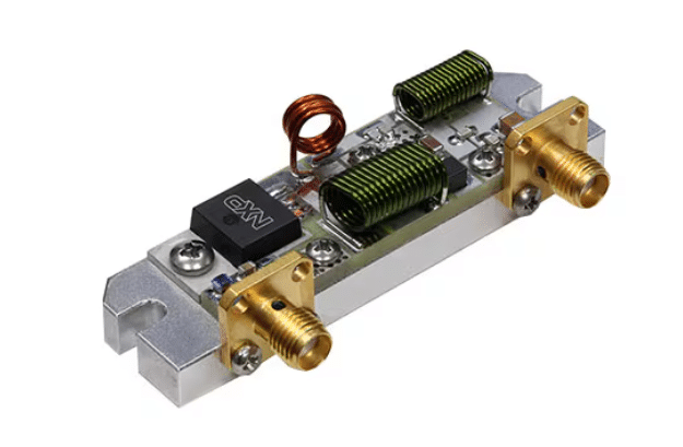
A ready-to-use RF energy amplifier reference design delivers as much as 100 W throughout 1.8 MHz to 250 MHz, that includes a reusable PCB structure, optimized thermal administration, and complete documentation for industrial, medical, and communication programs.

This reference design has been developed by NXP Semiconductors to offer engineers with a ready-to-use basis for high-performance RF energy amplifier programs. Its main objective is to scale back growth time, simplify prototyping, and guarantee constant outcomes throughout a variety of radio-frequency functions. By providing a validated and examined structure, the design allows engineers to concentrate on system integration and optimization reasonably than ranging from scratch.
NXP has launched the MRF101AN Reference Circuits, which help steady operation throughout a frequency vary of 1.8 MHz to 250 MHz, delivering output energy of as much as 100 W CW. This design emphasizes flexibility, effectivity, and ease of adaptation for a number of frequency bands. A significant benefit is the reusable PCB structure, which permits engineers to change a single design barely to swimsuit completely different working frequencies, saving each time and sources. The structure is optimized for balanced thermal efficiency, excessive linearity, and improved impedance matching, making it appropriate for a variety of business, medical, and communication functions. The reference design bundle additionally offers an entire implementation roadmap, together with circuit particulars, tuning suggestions, and measurement knowledge, which helps builders transition rapidly from prototype to manufacturing.
The reference design consists of a number of key options that make it sensible for real-world functions. It presents extensive frequency protection from 1.8 MHz to 250 MHz, excessive continuous-wave output energy as much as 100 W, and helps PCB structure reuse for a number of frequency bands. Moreover, it comes with full documentation, together with circuit overviews, tuning guides, take a look at knowledge, mechanical drawings, and efficiency graphs. These options enable engineers to combine the design effectively whereas sustaining excessive reliability and constant efficiency. Typical functions embody industrial, scientific, and medical (ISM) programs corresponding to plasma era, industrial heating, and medical RF ablation. It can be utilized in HF and VHF communication programs, together with transmitters and base stations, in addition to RF-based energy programs and switch-mode amplifiers the place steady high-frequency operation is important.
The structure of the design follows a simple RF sign chain: RF enter passes by means of an enter matching community, enters the amplifier part, after which passes by means of an output matching community to drive the load. Every stage is optimized to maximise energy switch, reduce sign reflection, and supply efficient thermal administration. Enter and output matching networks guarantee steady operation and preserve system effectivity throughout the frequency vary.
Together with the reference design, NXP offers a complete set of sources, together with schematic diagrams, PCB structure information, a invoice of supplies, measurement studies, tuning notes, and board images. These supplies enable engineers to duplicate and customise the design in accordance with their particular system necessities. The entire design bundle and associated documentation might be accessed right here.


