

This method makes use of a colour-changing LED (RGB LED/tri-colour LED) that switches to a brand new color each 5 seconds. Concurrently, the color title is displayed on an OLED mini display screen (SSD1306). This pairing helps learners join color names with the precise shades, making the method participating and pleasurable.
Color Buddy is a playful but instructional system that merges expertise with early childhood studying. It highlights how easy electronics might be changed into interactive studying aids for youngsters. Fig. 1 reveals the writer’s prototype. The Invoice of Supplies required to construct the system is listed in Desk 1.

| Desk 1 Invoice Of Supplies | |
| Title | Amount |
| Arduino Uno board | 1 |
| Widespread-cathode RGB LED | 1 |
| OLED show (SSD1306) | 1 |
| 220Ω resistor | 3 |
| 9V battery with connector | 1 |
| USB cable | For programming |
| Connecting wires | As required |
This circuit is designed for youngsters. It makes studying colors pleasurable by combining visible show and textual content, whereas additionally introducing freshmen to microcontrollers, LED color mixing, and I²C show management.

The thought is predicated on the precept that two completely different color combos can generate a brand new color. For instance, by including pink and inexperienced, yellow is produced. In an RGB LED, varied color combos generate a number of colored lights, and thru interfacing with the OLED, the title of the color is displayed on the display screen. Desk 2 reveals the color combos of an RGB LED.
| Desk 2 Color Mixtures of RGB LED | |||
| Color Title | Purple | Inexperienced | Blue |
| Black | 0 | 0 | 0 |
| Purple | 255 | 0 | 0 |
| Inexperienced | 0 | 255 | 0 |
| Blue | 0 | 0 | 255 |
| Yellow | 255 | 255 | 0 |
| Cyan | 0 | 255 | 255 |
| Magenta | 255 | 0 | 255 |
| White | 255 | 255 | 255 |
| Orange | 255 | 165 | 0 |
| Pink | 255 | 192 | 203 |
| Purple | 128 | 0 | 128 |
| Brown | 165 | 42 | 42 |
| Grey | 128 | 128 | 128 |
| Mild Blue | 173 | 216 | 230 |
| Lime | 0 | 255 | 0 |
| Darkish Inexperienced | 0 | 100 | 0 |
| Maroon | 128 | 0 | 0 |
| Navy | 0 | 0 | 128 |
| Olive | 128 | 128 | 0 |
| Teal | 0 | 128 | 128 |
Circuit and Working
Fig. 2 reveals the circuit of Color Buddy. It’s constructed round an Arduino Uno and powered by a 9V battery. It controls a common-cathode RGB LED and an OLED show. The battery connects to the Arduino’s DC jack, which regulates the voltage to 5V.
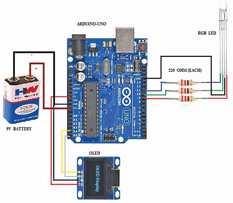
Every LED color pin (pink, inexperienced, blue) is linked to a digital output by way of a 220Ω resistor to restrict present. Utilizing excessive/low logic indicators or PWM, the Arduino mixes colors, altering the LED color each 5 seconds whereas updating the OLED with the corresponding color title.
An RGB LED accommodates three particular person LEDs—pink, inexperienced, and blue—packaged collectively in a single unit. Every LED is related to the Arduino by way of a separate 220Ω current-limiting resistor: the pink LED to pin 9, the inexperienced LED to pin 10, and the blue LED to pin 11. By adjusting the brightness of every color utilizing PWM, a various set of colors might be generated.
One other element used on this system is the two.4cm (0.96-inch) OLED show (I²C, SSD1306), related to the Arduino through the I²C interface. The VCC pin is related to the Arduino’s 5V pin, GND to GND, SDA (Serial Information) to analogue pin A4, and SCL (Serial Clock) to analogue pin A5, following the usual I²C pin configuration on the Arduino Uno.
Its operation entails the Arduino controlling each the RGB LED and the OLED concurrently. The OLED can show messages, sensor readings, or system standing, whereas the RGB LED offers visible colour-based suggestions. Collectively, this association might be utilized to interactive or ornamental programs the place each visible show and colored gentle indications are required.
Arduino Code
The software program for this method is developed within the Arduino IDE, utilizing C/C++ programming to manage the RGB LED and show data on the OLED display screen. The RGB LED is pushed utilizing three PWM pins (9, 10, and 11), permitting brightness management of every color channel to supply a variety of colors. The code contains features to set particular person LED colors and create transitions or results. Timing features like delay() can be utilized to manage the velocity of color adjustments, whereas loops deal with repeated sequences.
For the OLED show, the Adafruit SSD1306 and Adafruit GFX libraries are used to initialise and draw textual content, shapes, or photos. The OLED is related through the I²C interface (SDA to A4, SCL to A5), and the libraries deal with all low-level communication with the show controller. These libraries make it easy to show sensor readings, system standing, or messages alongside the RGB LED color results. This system’s setup() operate initialises the OLED show and units pin modes for the RGB LED, whereas the loop() operate constantly updates the LED color and OLED content material based mostly on the programmed logic.

Building and Testing
The circuit might be assembled both on a breadboard for prototyping or on a general-purpose PCB for everlasting use. For breadboard meeting, the Arduino Uno is positioned individually, and jumper wires are used to attach the RGB LED and OLED show module, as proven in Fig. 2. For PCB meeting, the identical connections are soldered, making certain appropriate polarity for the LED and correct resistor placement, whereas protecting monitor widths ample for secure connections.
For testing, the supply code is uploaded into the Arduino Uno utilizing a USB cable and a laptop computer or desktop. The meeting is then accomplished after eradicating the USB cable. The circuit is powered by a 9V battery related to the Arduino’s DC jack.
Throughout testing, the RGB LED cycles by way of completely different colors each 5 seconds as PWM indicators are despatched to pins 9, 10, and 11, whereas the OLED concurrently shows the corresponding color title. If any color or show output is wrong, wiring continuity must be checked, resistor values verified, and the OLED’s I²C deal with confirmed. As soon as examined and verified, the system operates as supposed, offering synchronised LED color adjustments and matching textual content descriptions on the OLED.
Rakesh Jain, Assistant Professor in ECE Division in Geetanjali Institute of Technical Research, Udaipur, holds a grasp’s diploma in VLSI, BE diploma in electronics and communication, and diploma in electronics. His analysis areas are sensors and microcontrollers, and he has 31 copyrights, 9 design patents registration, 4 Indian utility patents, and 18 DIY articles revealed in EFY to his credit score. He’s recipient of Mewar Scientist Award 2023.
