

Designing a circuit to change on a lightweight at nightfall and off at daybreak is simple, and lots of such designs have been featured in EFY. Nonetheless, lights managed this fashion stay on all evening, leading to wasted electrical energy and lowered lamp lifespan. In most houses and enterprise premises, out of doors lights are turned on at nightfall and switched off after a number of hours. The gadget described right here automates this course of, activating the sunshine within the night and switching it off after 2 to six hours. This strategy is especially efficient for securing locked houses, because the timed lighting creates the phantasm of occupancy and deters potential intruders.

| Elements Record |
| Semiconductors: IC1 (IC1A, IC1B) – LM358 twin op-amp T1 – 2N3904 NPN transistor D1-D5 – 1N4007 rectifier diode LED1, LED2 – 5mm LED Resistors (all 1/4-watt, ±5% carbon): R1, R2, R6, R8 – 10kΩ R3 – 4.7kΩ R4, R7 – 1kΩ R5 – 560Ω Capacitors: C1 – 1F, 2.7V tremendous capacitor C2 – 220µF, 25V electrolytic Miscellaneous: CON1-CON3 – 2-pin connector Batt.1 – 12V battery/12V adaptor RL1 – 12V, SPST relay LDR1 – Small light-dependent resistor – 60-watt bulb for lamp |
Circuit and dealing
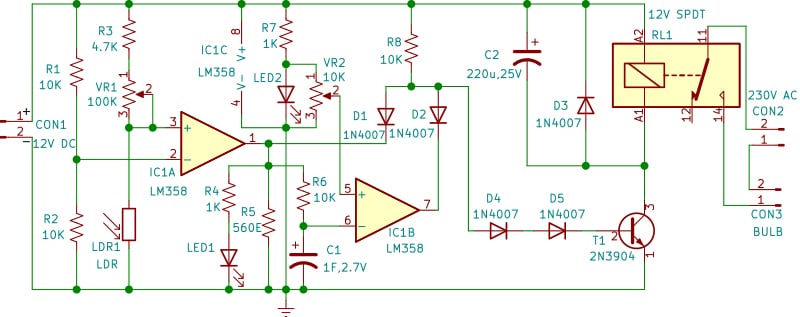
Fig. 2 exhibits the circuit diagram of the automated night mild. It’s constructed across the twin op-amp IC LM358. The primary op-amp, constructed round IC1A, is used as a comparator. The inverting pin 2 of the comparator is biased at half the provision voltage by resistors R1 and R2. Throughout the daytime, the resistance of the LDR linked to the non-inverting pin 3 of the comparator is low. The voltage on the non-inverting pin 3 is decrease than the voltage on the inverting pin 2, so the output at pin 1 of the comparator is low.
Within the night, the resistance of the LDR will increase and turns into greater than the resistance of R3 plus VR1, and the output at pin 1 of the comparator turns into excessive (that’s, about 1.5 volts beneath the provision voltage). Potentiometer VR1 serves as sensitivity management.

The second op-amp is constructed round IC1B of IC LM358. Its inverting enter pin 6 is linked to supercapacitor C1. Resistor R4 and LED1 drop the output of comparator IC1A at pin 1 to the ahead voltage of LED1, which is about 2V. This voltage is used to cost the supercapacitor by means of resistor R6. This protects the supercapacitor from injury as a consequence of excessive voltage and ensures that it’s charged at a relentless charge, regardless of provide voltage fluctuations.
The non-inverting enter pin 5 of the second comparator IC1B is linked to the ahead voltage of LED2 by means of potentiometer VR2. LED2 additionally acts as a power-on indicator. Initially, the supercapacitor C1 is discharged, and the voltage on the non-inverting enter pin 5 is greater than the voltage on the inverting enter pin 6, so the output at pin 7 of the second comparator IC1B is excessive.

Thus, within the night, the outputs of each comparators IC1A and IC1B are excessive. The outputs of each comparators are utilized to transistor T1 by means of diodes D1 and D2 and pull-up resistor R8, which perform as an AND gate. This conducts the transistor T1 to change on the sunshine by means of the contacts of relay RL1.
After a number of hours, the voltage at supercapacitor C1 exceeds the voltage utilized to the non-inverting pin 5 of the second comparator, and the output at pin 7 turns into low. This cuts off transistor T1 and switches off the sunshine. The output of the primary comparator stays excessive and LED1 continues to glow, and C1 continues to cost.
Within the morning, the output of the primary comparator additionally turns into low and LED1 turns off. Tremendous capacitor C1 now begins discharging by means of R6 and R5. By the night, C1 is totally discharged, and the circuit is prepared once more for the following working cycle. R5 is crucial to make sure that C1 discharges even when the facility provide is on. The gadget doesn’t should be reset within the daytime and can proceed to change on the sunshine each night for a number of hours with out human intervention in a locked home.
Experimentally, it has been noticed that the output of the comparators, when low, will not be zero volts. A small voltage—about 0.8 volts—exists on the output of the comparators when the output is low. As a consequence of diodes D1 and D2, which type a part of the AND gate, the voltage on the junction of the anodes of D1, D2, and D4 is round 1.3 to 1.4 volts, even when the output of both comparator is low. That is ample to activate transistor T1. Therefore, D4 and D5 are linked within the base circuit to soak up this voltage and make sure that the transistor conducts solely when the output of each comparators is excessive.
Building and testing
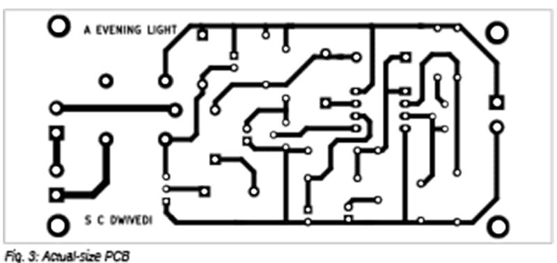
An actual-size, single-sided PCB format for the automated night mild is proven in Fig. 3, with its part format in Fig. 4. After assembling the circuit on the PCB, enclose it in an acceptable field, positioning all of the switches and LEDs on the highest of the field. Repair the LDR on the highest of the field. Mount CON1 on the entrance aspect of the field. Mount CON2 and CON3 on the again aspect of the field. The gadget will also be assembled on a general-purpose board or a Veroboard.
Preserve the wiper of VR2 in the direction of the anode of LED2 in order that about 2 volts are utilized to the non-inverting enter of IC1B. Within the night, regulate VR1 in order that LED1 and the lamp activate. After a number of hours, regulate VR2 in order that the sunshine switches off.

Lower-off time calibration
The output of comparator IC1A shall be excessive in darkness. The output of comparator IC1B will stay excessive so long as the voltage at C1 is decrease than the voltage on the wiper of VR2, which is linked to pin 5 of IC1B. The supercapacitor C1 will cost to 63.2% of the LED1 voltage (2V), which is roughly 1.264V, after 10,000 seconds (or 2 hours and 47 minutes), and to 86.5% of the LED1 voltage (roughly 1.73V) after 20,000 seconds (or 5 hours and 33 minutes).
Due to this fact, the length for which the lamp stays on will be set by adjusting the voltage on the wiper of VR2. For instance, to change the sunshine off 2 hours and 47 minutes after it activates within the night, set the voltage at pin 5 of IC1B to 1.264V utilizing VR2. This permits the calibration of the switch-off time between 2 to six hours utilizing VR2.
Pradeep Vasudeva is a member of the Indian Forest Service, presently posted as Director, State Forest Analysis Institute, Jabalpur. Electronics has been his ardour since adolescence, and his areas of curiosity embody newbie radio, RF circuits, and audio tasks.
