
Let’s Soften Metals Utilizing the ZVS (Zero Voltage Switching) Approach Utilized to a 1,000W RLC Resonant Circuit Have you ever ever puzzled how intense the electromagnetic fields surrounding us could be?
It is a related query, contemplating we’re surrounded by numerous electromagnetic waves, attributable to energy distribution cables, radio and TV transmitters, cell phone networks, and distant controls. Attempt inserting a cell phone close to a landline handset or a speaker, and also you’ll hear crackling.
Or stroll beneath a high-voltage energy line in the dead of night with a fluorescent tube and see it lights up. These waves, invisible to the human eye, are very a lot current in our each day lives.
Though their results turn out to be important solely in sure circumstances and relying on the irradiated energy and our proximity to the supply. However how highly effective can an electromagnetic discipline be? The microwave oven in our kitchens proves that it might warmth meals and even produce electrical arcs between the ends of aluminum foil or metallic objects.
Might such a discipline be sturdy sufficient to convey a metallic conductor to incandescence in just a few seconds? The reply is sure, and right now’s undertaking clearly demonstrates this. It’s a system that operates utilizing three bodily rules that electronics lovers will know from college: magnetic induction, eddy currents, and the Joule impact.
Our undertaking demonstrates the way to warmth and even soften electrically conductive and particularly ferromagnetic supplies utilizing a ZVS-type circuit with a nominal energy of 1,000W, which may rise to 1,500W beneath sure situations. ZVS stands for Zero Voltage Switching, a way utilized in energy electronics converters to enhance effectivity.
It permits semiconductor switches to vary state with near-zero voltage throughout their terminals, minimizing the ability loss (V x I), as we’ll clarify within the working rules part. This idea is the idea for induction cooktops, extensively used overseas in international locations with low-cost electrical energy.
An induction cooktop consists of a coil by means of which a excessive alternating present flows, producing a magnetic discipline proportional to the present.
Based on Faraday’s legislation, a time-varying magnetic flux induces an electromotive pressure in any electrically conductive physique intersected by the ensuing discipline traces.
This EMF generates eddy currents throughout the materials of the pots or containers positioned on the cooktop. These currents are additionally referred to as “Eddy currents” (eddy that means “vortex” in English), as a result of swirling sample contained in the conductor.
These parasitic currents trigger the Joule impact—warmth generated on account of vitality loss. In induction cooktops, the warmth warms the pot, much like how friction dissipates kinetic vitality as warmth in mechanical programs. Induction cooking is a selected case: the impact of electromagnetic fields differs primarily based on magnetic permeability, reluctance, and conductivity of the supplies concerned.
That explains why a steel pot (particularly metal) can’t be utilized in a microwave oven, however meat could be cooked. Conversely, on an induction cooktop, meat received’t warmth except it’s inside a steel-based pot. Within the microwave, warmth is generated contained in the meals, whereas in induction cooktops, it happens within the pot’s base. Some supplies warmth successfully at low frequencies; others require microwave frequencies.
Usually, eddy currents are undesirable (as in transformer core losses), however in our case, we improve them to generate warmth within the materials affected by the magnetic discipline. Particularly, ferromagnetic supplies warmth considerably even on the working frequency of the circuit.
Moreover heating and melting metals, the circuit has different attention-grabbing functions, akin to wi-fi energy switch utilizing coupled coils tuned to the resonance frequency and Tesla coil ignition circuits.
Induction Heater Circuit Diagram
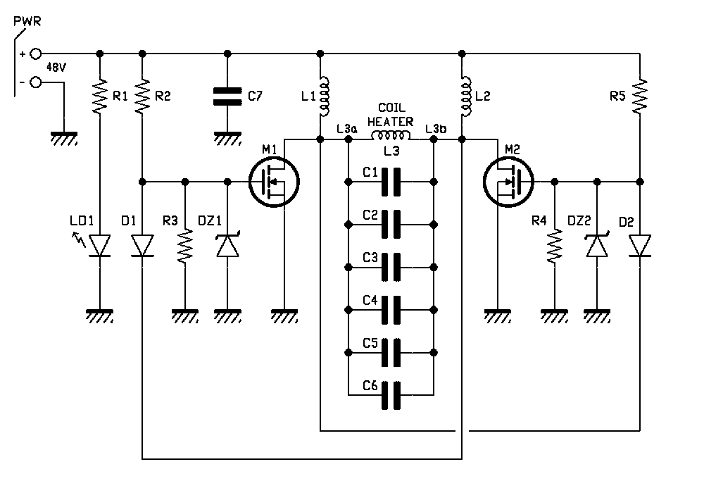
By observing the circuit diagram, we will see a symmetrical two-branch construction within the management circuit, often called a Royer oscillator, which allows self-oscillation of an RLC block at its pure resonance frequency.
The RLC block consists of an inductor (generally referred to as the “work coil”), a capacitor financial institution (referred to as the “tank capacitor”), and the sequence resistance launched by the parts and wiring.
As soon as powered, the oscillator enters resonance. The excessive resonance present flowing within the work coil generates a powerful magnetic discipline.
When the Royer oscillator is powered, even when symmetric, one of many two MOSFETs (M1 or M2) will begin conducting first on account of manufacturing variations. Assume M1 begins first—its drain is pulled to floor potential, forcing M2 off by way of the suggestions diode D1, which rapidly discharges the gate of M2.
The resonant circuit composed of inductor L3 and capacitors C1 by means of C6 presents a sinusoidal half-wave at M2’s drain, going from zero to peak and again to zero. Because it returns to zero, D2 conducts, turning M1 off and switching M2 on, producing the alternative sinusoidal half-wave.
This cycle repeats on the pure resonance frequency of the RLC block. The L3 work coil carries a excessive sinusoidal present round 100 kHz. Whereas this frequency produces delicate heating in meals, it already generates important heating in a metal bolt, rising with accessible energy and induced electromagnetic discipline.
The MOSFETs function in push-pull: when M1 is on, M2 is off and vice versa. That is ensured by the resonant circuit and suggestions diodes D1 and D2. Simultaneous conduction would short-circuit the provision, destroying the MOSFETs.
MOSFET switching happens with almost zero Vds (drain-source voltage), i.e., Zero Voltage Switching (ZVS), minimizing switching losses:
Pd = Vds x Id
the place Id is the drain present.
ZVS additionally considerably reduces the high-frequency noise naturally emitted by switching circuits.
MOSFETs M1 and M2 are Infineon IRFP260N, that includes a really low Rdson (solely 40 mΩ) and excessive drain present (ID = 50A). They’re Quick Switching sorts, switching rapidly from full conduction (on) to cutoff, together with their antiparallel safety diodes with a TRR (Reverse Restoration Time) round 400 ns.
The height voltage in a ZVS switching circuit is calculated as:
VPEAK = SUPPLY VOLTAGE x π
For the reason that provide voltage is proscribed to 48 VDC, the utmost drain-source voltage (Vdss) is chosen as 200V.
The suggestions diodes D1 and D2 are MUR420, additionally Quick Switching, able to carrying no less than 4A and rapidly turning off the related MOSFET by discharging the gate.
The GATEs of the 2 MOSFETs are pushed by energy resistors R2 and R5, every valued at 470 ohms.
To guard the MOSFETs from overvoltage and overcurrent, two Zener-resistor pairs are used: R3/DZ1 and R4/DZ2. R3 and R4 are 10 kohms; DZ1 and DZ2 are 12V – 1W.
LED LD1 signifies the presence of energy and is powered by means of the sequence resistor R1, 4.7 kohms, to restrict present.
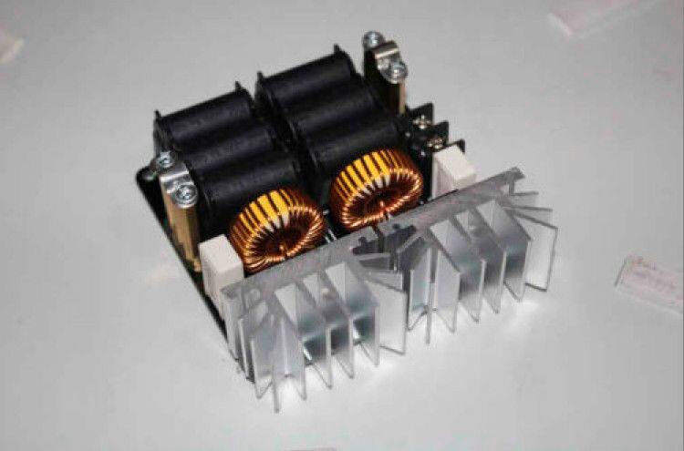
Inductors L1 and L2 are 100 µH and serve to suppress switching voltage spikes (“spikes”) that might destroy the MOSFETs. They’re wound on toroidal cores with a most present ranking of 13A.
Capacitors C1, C2, C3, C4, C5, C6 are MKP polypropylene capacitors, chosen for his or her capacity to face up to excessive currents and voltages throughout resonance whereas minimizing losses.
On this design, the resonance capacitance is roughly 2 µF, achieved by paralleling six 0.33 µF capacitors rated at 630V.
The work coil (Fig. 1), into which the article to be heated/melted is positioned, is product of 6 turns of 6 mm diameter hole copper tube with 0.8 mm wall thickness. It’s air-wound to deal with excessive currents, dissipate generated warmth successfully, and scale back pores and skin impact losses at 100 kHz.
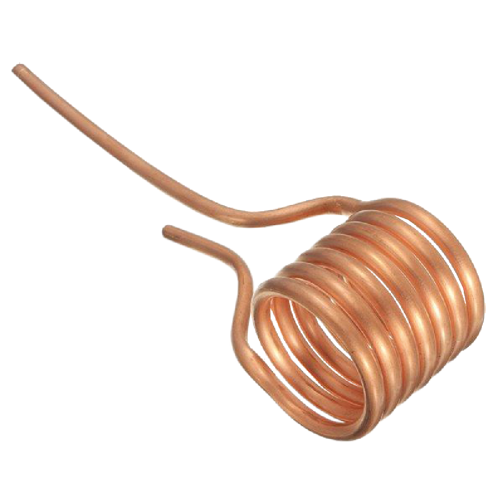
The turns should not contact one another (because the copper is naked), in any other case quick circuits will kind, decreasing the variety of efficient turns and altering inductance.
The theoretical inductance of the work coil is about 1.26 µH, although this may occasionally fluctuate relying on the size of the horizontal leads related to the capacitors.
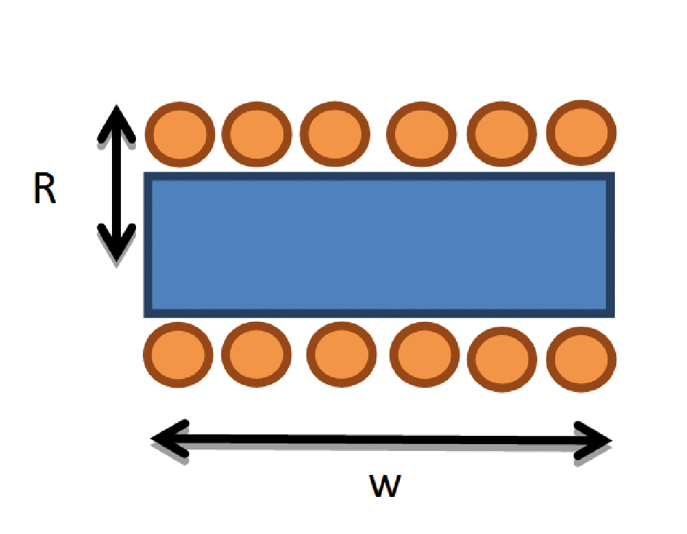
To calculate the theoretical self-inductance, you should use the components (seek advice from Fig. 2):
L = µ₀ * N² * π * R² / w
The place µ₀ is the permeability of free area (µ₀ = 4π * 10⁻⁷ H/m),
N is the variety of turns (in our case, 6),
R = 2.5 x 10⁻² m and w = 7 x 10⁻² m, therefore L ≈ 1.26 µH.
To calculate the theoretical resonance frequency, use the components:
fR = 1 / (2π * √(L * C)) = 100.3 kHz
The place L = 1.26 µH, C = 2 µF.
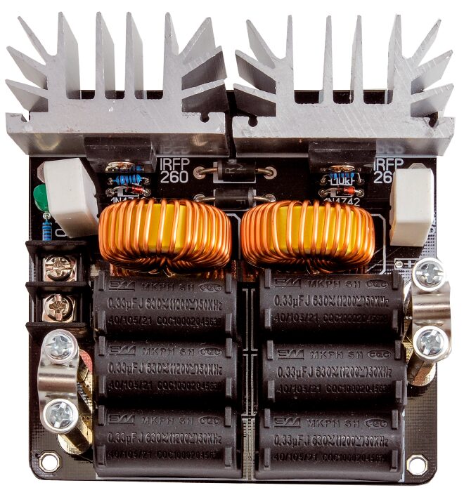
Meeting Format
Part Record
C1: 0.33 µF 630 V~ pitch 30mm
C2: 0.33 µF 630 V~ pitch 30mm
C3: 0.33 µF 630 V~ pitch 30mm
C4: 0.33 µF 630 V~ pitch 30mm
C5: 0.33 µF 630 V~ pitch 30mm
C6: 0.33 µF 630 V~ pitch 30mm
C7: -
R1: 4.7 kohm
R2: 470 ohm 5W
R3: 10 kohm 1%
R4: 10 kohm 1%
R5: 470 ohm 5W
L1: 100 µH inductor
L2: 100 µH inductor
L3: 1.26 µH coil
M1, M2: IRFP260N
D1: MUR420
D2: MUR420
DZ1, DZ2: 1N4742
DL1: 5 mm inexperienced LED
Sensible Meeting
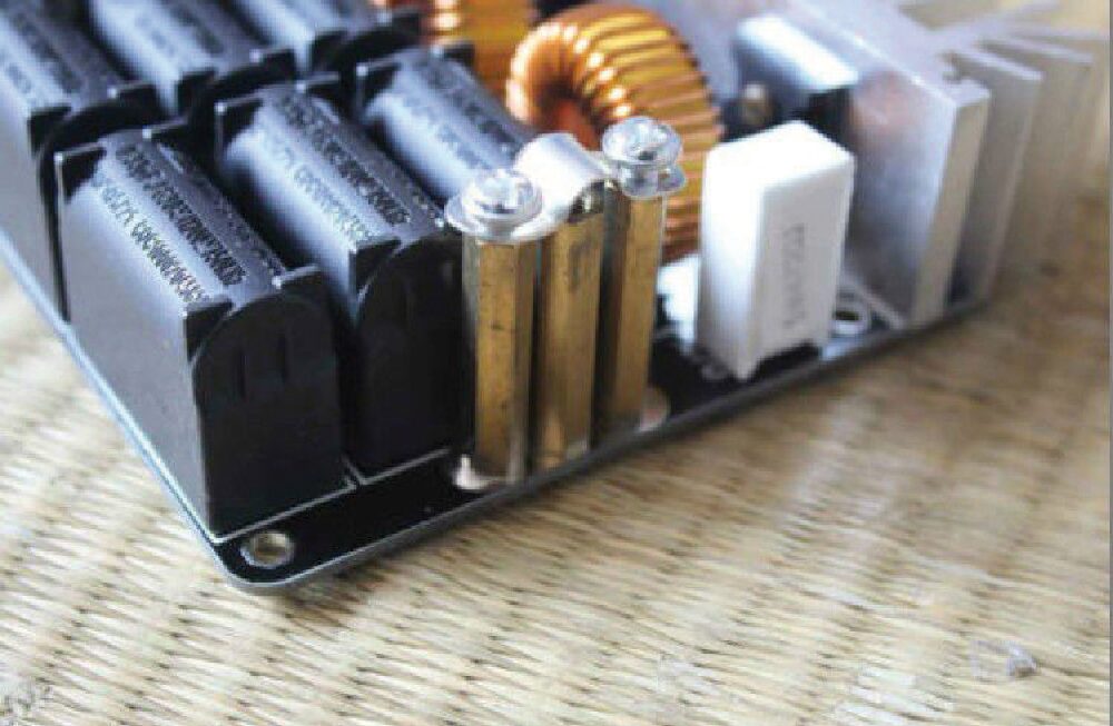
To mount the coil, three 6 mm golden hexagonal standoffs, every 40 mm lengthy, are used. The 2 lateral ones are mounted (utilizing 4MA screws) with an iron clamp that secures the ends of the work coil. Loosen the screws holding the 2 standoffs (Fig. 4), insert the ends of the work coil into the steel assist in order that the coil is oriented towards the ability provide terminal block marked + / -.
Place the work coil in order that lower than 1 cm of tubing extends from the standoff assist, and tighten the screws (Fig. 5).
Measurements
The present circulating by means of the work coil has an RMS worth of roughly 100 A.
With such a excessive present, the magnetic discipline is important, and all close by objects are uncovered to its discipline traces—therefore, delicate digital units may expertise interference.
The magnetic flux density B could be calculated with the components:
B = µ₀ * N * I / L = 10.7 mT = 107 gauss
The place N = 6, I = 100 A, and L = 1.26 µH.
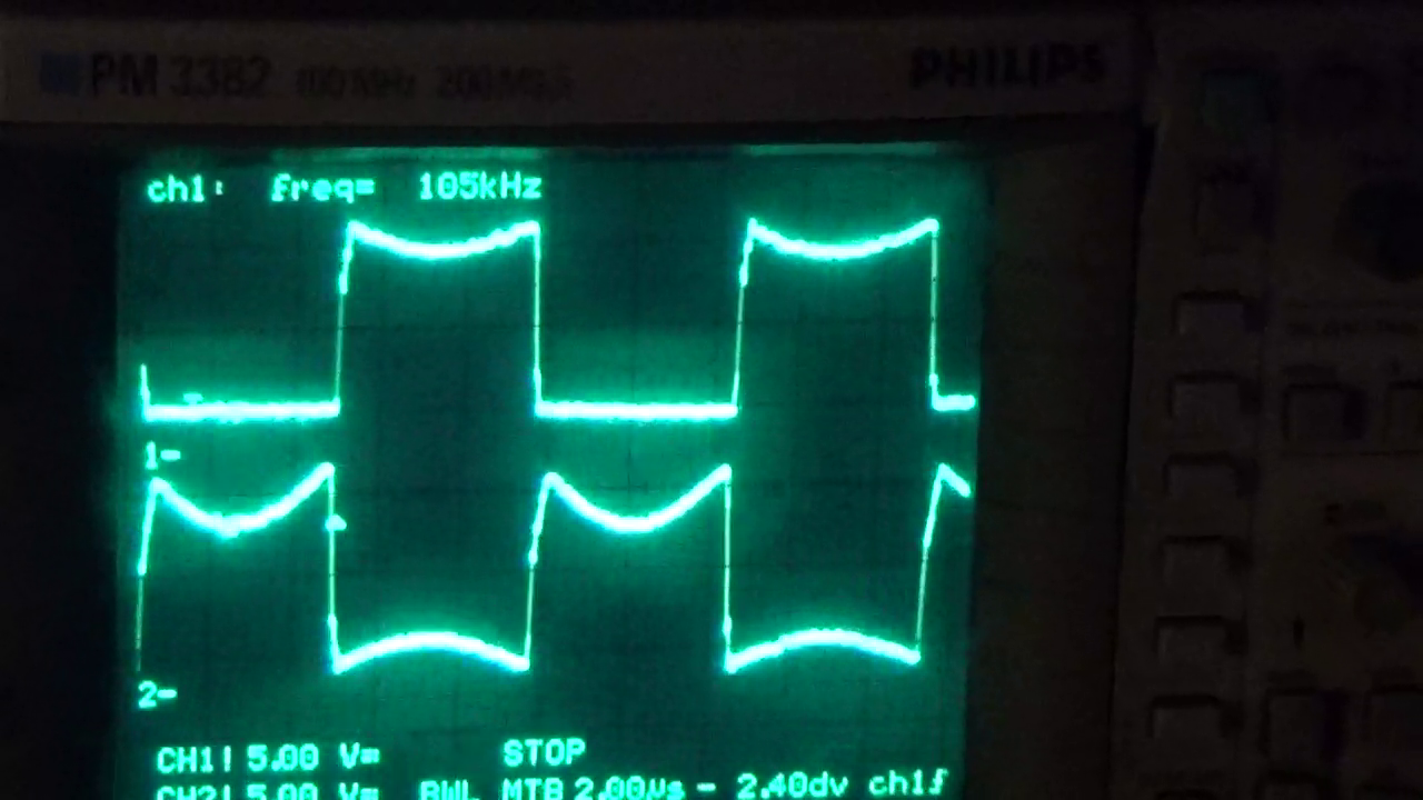
Fig. 7 reveals the oscilloscope waveforms of the GATE-SOURCE voltages of M1 and M2. As could be seen, they’re completely in antiphase:
Earlier than the GATE voltage of M2 reaches the excessive stage and M2 turns absolutely on, M1’s GATE voltage is already low, making certain M1 is off and stopping simultaneous conduction, which might destroy the MOSFETs.
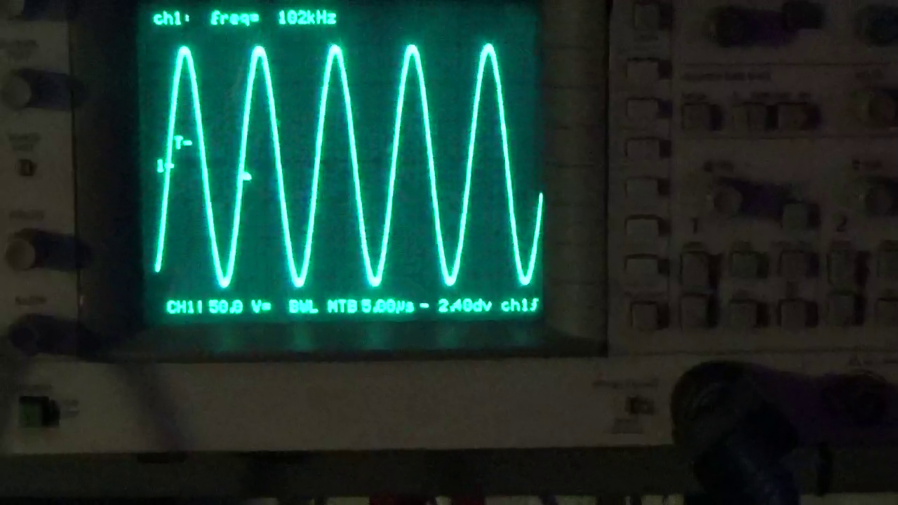
Fig. 8 reveals the voltage utilized to the work coil, reaching round 150V peak and sustaining a wonderfully sinusoidal waveform, due to the parallel RLC resonant circuit.
Lastly, Fig. 9 reveals the present drawn by the circuit at an enter voltage of 48 VDC, which is roughly 17 A.
The measurement was made by detecting the voltage drop throughout a 0.06 ohm shunt resistor (obtained by paralleling three 0.18 ohm resistors) utilizing a digital multimeter, with a steel object inserted within the work coil.
We want you good luck and remind you as soon as once more: with correct care and a spotlight, this circuit can give you spectacular and rewarding experiences.
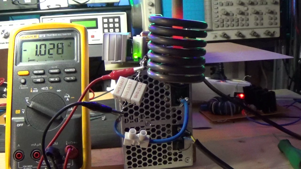
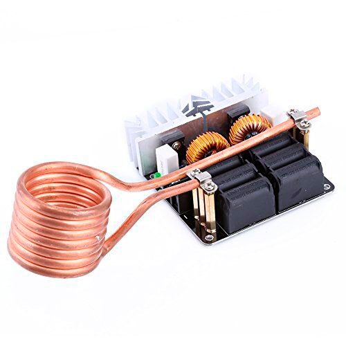
Fig. 5 Work coil mounted on the circuit.
Utilization
The circuit have to be powered with a DC voltage between 10 and 48 V and with ample energy. If utilizing the utmost voltage of 48 VDC, we suggest an influence provide rated no less than 1,500 W.
Insert the optimistic and damaging wires of the ability provide into the terminal block, checking the polarity, and tighten the screws.
Energy the circuit by way of terminals + and – and verify that the inexperienced LED LD1 lights up, indicating enter voltage presence.
At this level, the resonance present begins flowing by means of the work coil at roughly 100 kHz.
If powered on the full 48 VDC with none steel object contained in the work coil, energy consumption stays beneath 500 W;
nonetheless, when a conductor is inserted, relying on its materials, dimension, form, and place, energy consumption can fluctuate vastly as much as 1,500 W.
Select the conductor to be inserted—like a steel screw—maintain it with pliers (don’t get too near the coil) to keep away from burns.
Insert the conductor slowly into the work coil, making certain it doesn’t contact the interior coil partitions.
Preserve the conductor vertical contained in the work coil.
The inserted conductor acts because the transformer’s secondary, with the work coil being the first winding. Being inside a solenoid, the conductor is uncovered to a powerful magnetic discipline.
Inside seconds, as a result of Joule impact, the conductor heats up and glows with typical incandescent orange-yellow tones (Fig. 6).
This situation could be maintained for tens of seconds. Nonetheless, be extraordinarily cautious as temperatures rise quickly—don’t contact the conductor, coil, or heatsinks on to keep away from burns.
After a number of minutes of use, the work coil will start to darken, finally turning almost black from the warmth generated. This is not going to have an effect on its efficiency.
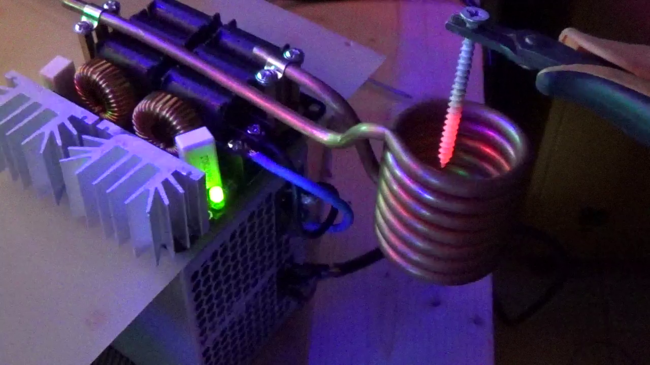
Fig. 6 Place the article contained in the coil.

